-40%
LOT OF 5 Allegro A3953SB-T DC Motor Driver Full Bridge PWM -GENUINE ALLEGRO
$ 6.6
- Description
- Size Guide
Description
LOTOF
5
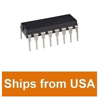
Allegro A3953SB-T DC Motor Driver Full Bridge PWM,, 16-Pin PDIP
NEW IN TUBES - GENUINE Allegro Microsystems-
NOT CHINA FAKES
OBSOLETE HARD TO FIND- THESE ARE PRIME AND NEVER USED OLD STOCK
THIS ITEM COMES WITH A 100% GUARANTY YOU WILL FIND IT TO BE NEW AS LISTED.
BUY WITH CONFIDENCE - I HAVE 100% SATISFIED CUSTOMERS, SEE MY FEEDBACK
http://pdf1.alldatasheet.com/datasheet-pdf/view/55109/ALLEGRO/A3953SB.html
Application Full Bridge PWM Motor Driver
Dimensions 19.05 x 6.35 x 3.3mm
Height 3.3mm
Length 19.05mm
Maximum Operating Supply Voltage 5.5 V
Maximum Operating Temperature +85 °C
Minimum Operating Supply Voltage 3 V
Minimum Operating Temperature -20 °C
Mounting Type Through Hole
Package Type PDIP, PDIP Bat
Pin Count 16
Width 6.35mm
Designed for bidirectional pulse-width modulated (PWM) current control of inductive loads, the A3953S-- is capable of continuous output currents ±1.3 A and operating voltages 50 V. Internal fixed off-time PWM currentcontrol circuitry can be used to regulate the maximum load current to a desired value. The peak load current limit is set by the user's selection of an input reference voltage and external sensing resistor. The fixed off-time pulse duration is set by a user- selected external RC timing network. Internal circuit protection includes thermal shutdown with hysteresis, transient-suppression diodes, and crossover current protection. Special power-up sequencing is not required. With the ENABLE input held low, the PHASE input controls load current polarity by selecting the appropriate source and sink driver pair. The MODE input determines whether the PWM current-control circuitry operates in a slow current-decay mode (only the selected source driver switching) in a fast current-decay mode (selected source and sink switching). A user-selectable blanking window prevents false triggering of the PWM current-control circuitry. With the ENABLE input held high, all output drivers are disabled. A sleep mode is provided to reduce power consumption. When a logic low is applied to the BRAKE input, the braking function is enabled. This overrides ENABLE and PHASE to turn off both source drivers and turn on both sink drivers. The brake function can be used to dynamically brake brush dc motors. The A3953S-- is supplied in a choice of two power packages; a 16-pin dual-in-line plastic package with copper heat-sink tabs, and a 16-pin plastic SOIC with copper heat-sink tabs. For both package styles, the power tab is at ground potential and needs no electrical isolation. Each package type is available in a lead-free version (100% matte tin leadframe).
Note the A3953SB (DIP) and the A3953SLB (SOIC) are electrically identical and share a common terminal number assignment.
Load Supply Voltage, VBB. 50 V Output Current, IOUT (Continuous). ±1.3 A* Logic Supply Voltage, VCC. 7.0 V Logic/Reference Input Voltage Range, VIN. V to VCC 0.3 V Sense Voltage, VSENSE (VCC = 5.0 V). 1.0 V (VCC = 3.3 V). 0.4 V Package Power Dissipation, PD. See Graph Operating Temperature Range, TA. to +85°C Junction Temperature, TJ. +150°C Storage Temperature Range, TS. to +150°C
* Output current rating may be limited by duty cycle, ambient temperature, and heat sinking. Under any set of conditions, do not exceed the specified current rating or a junction temperature of 150°C. Fault conditions that produce excessive junction temperature will activate the device's thermal shutdown circuitry. These conditions can be tolerated but should be avoided.
FEATURES
Sleep (Low Current ±1.3 A Continuous Output Current Consumption) Mode 50 V Output Voltage Rating Internal 5.5 V Logic Supply Voltage Suppression Diodes Internal PWM Current Control Internal ThermalSaturated Sink Drivers (Below 1 A) Shutdown Circuitry Fast and Slow Current-Decay Modes Crossover-Current Automotive Capable and UVLO Protection
Part Number A3953SLB A3953SLB-T Package 16-Pin DIP 16-Pin DIP, Lead-Free 16-Lead SOIC 16-Lead SOIC, Lead-Free RJA 43°C/W 67°C/W RJT 6°C/W
BRAKE ENABLE PHASE MODE OUTA Off OUTB Off Sleep Mode Standby Forward, Fast Current-Decay Mode Forward, Slow Current-Decay Mode Reverse, Fast Current-Decay Mode Reverse, Slow Current-Decay Mode Brake, Fast Current-Decay Mode Brake, No Current Control DESCRIPTION
Limits Characteristic Symbol Test Conditions Min. Typ. Max. Units
Load Supply Voltage Range Output Leakage Current VBB ICEX Operating, IOUT 3 mH VOUT = VBB VOUT 0 V Sense Current Offset Output Saturation Voltage BRAKE = H (Forward/Reverse Mode) ISO VCE(SAT) ISENSE - IOUT1, IOUT = 850 mA, VSENSE 0 V, VCC 5 V VSENSE 0.4 V, VCC 3.0 V: Source Driver, IOUT -0.85 A Source Driver, IOUT -1.3 A Sink Driver, IOUT 0.85 A Sink Driver, IOUT 1.3 A Output Saturation Voltage BRAKE = L (Brake Mode) Clamp Diode Forward Voltage (Sink or Source) VF VCE(SAT) VSENSE 0.4 V, VCC 3.0 V: Sink Driver, IOUT 0.85 A Sink Driver, IOUT = 1.3 VCC µA mA
Datasheets A3953
Product Photos 16-Dip-X
Standard Package ? 25
Category
Integrated Circuits (ICs)
Family
PMIC - Motor, Bridge Drivers
Series -
Packaging ? Tube ?
Motor Type - Stepper Bipolar
Motor Type - AC, DC Brushed DC
Function Driver - Fully Integrated, Control and Power Stage
Output Configuration Full H-Bridge, (1) Single
Interface Parallel
Applications General Purpose
Current - Output 1.3A
Voltage - Supply 3 V ~ 5.5 V
Voltage - Load 3 V ~ 50 V
Operating Temperature -20°C ~ 85°C
Mounting Type Through Hole
Package / Case 16-PowerDIP (0.300", 7.62mm)
Supplier Device Package 16-DIP
Other Names 620-1065


